Good to go.
Rohans got the file if anyone’s interested.
Print and play.
Good to go.
Rohans got the file if anyone’s interested.
Print and play.
With the growing use of 3D printing and improvements in the speed, cost, quality and material choice I thought it might be a good idea to get some open source files together that people could use.
The first one I will offer up is a fin base for people who want to make wooden single fins but find the base tedious and difficult to build. PM me if you want the file or if you have a website where you can post it for anyone to download.
In the coming weeks I will try and get around to looking at modelling a fin base that will hold an FCS fin and one that will hold a Futures fin.
Please remember that these will be untested designs, but I have done my best to design them as well as I can first time. If you find issues with any of them and can convince me that revisions are required then I will adjust the design accordingly.
Please choose your printing material wisely also.
very very cool guys!
Or for those who prefer to insert a 1/8" (3.2mm) sheet of ply or fibreglass as the fin support tab from beneath (as suggested on the Universal Fin System thread) you can have this one, which will probably be stronger (and certainly cheaper to print).
I like this one more because it has a central piece that runs thru the whole height of the assembly.
What you insert could be ply, glassed ply or carbon fibre laminate over wood.
It then gives a ‘like to like’ bond to the surrounding material that becomes the fin blade.
Also good if you like your tab forward or at the back.
And its a great blank if have a hankering do do something totally different…know what I mean ?
Terrific CADwork Rohan !!
Brilliant.
RDM
Nice work and thanks for sharing. Are your designs intended to have the glassing stop at your base or have fiberglass cover the wood fin and the base? 9.2mm is the exact width of the box and won’t allow for fiberglass to cover your base and still fit in the box. Not having glass cover the wood and base will be a spot of weakness.
Be well
Dave
Hi Dave.
Neither are designed for glass over the outside of the box. And you are correct, strength may be an issue. But until someone makes one and tests it we won’t know.
It’s easy enough to make variations which would be able to be glassed over if that’s want you want. What sort of thickness would you like the base taken down to ? 7.2mm? Remember that the glassing will get tricky though when you transition say from the trailing edge of the fin on to the base with that bit of a step.
I have also made a version of the “insert” design which has a 4mm width slot for those of you who prefer metric width material.
Cheers
Rohan
great stuff Rohan !!
cheers for sharing this , I look forward to seeing some of the results , and hearing how they surf.
I currently have three or four old snapped single fins of my brother’s lying around [did I show you , I forget ?] , that bases would be good for …
I just need to find out , when he returns , if he has any plans for them , himself [you know me mate … the fins [and boards ] recycler !!]
Or if you prefer the reverse insertion method where you build the fin with the tab already in it, I have this (in 1/8" (3.2mm), 4mm and 6mm slot width versions).
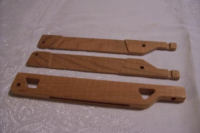
Nice work RDM! RDM’s model 1 insert style below, my 2-piece variant on top. Mostly machined from cedar, a couple mods by hand. RDM’s fits nicely in the box on my board. -J
Wow J !
Talk about taking the ball and running with it. Beautiful work.
Rohan,
I build my base by hand then glass over the wood fin and base with 2x 6oz glass on both sides. I also account for a hotcoat over the base. Of course my numbers are going to be different than everyone else but I aim for something close to .30’’ before I start glassing.
jrandy,
Those look amazing. Nice work
Dave
Thanks for the compliments Dave and Rohan. The mill does a nice job when I remember to push the right buttons. Rohan’s piece is all him except I had to rotate it to add the slot and screw hole freehand since I did not want to write a second program. Mine keeps the mill running in the same plane but needs a little work on the pinning back together scheme.
Ben, I have a busted fin I would like to try these on too.
It’s been fun reading the banter on these two threads. -J
Yes Jim, the two threads have been quite unique,
1/ something actually NEW has been built
and
2/ no ones jumped in and said its been done before.
The only part missing is the 80 or 90 emails between Rohan and I. But he’s able to take a basic drawing and turn it into a real product. All credit to Rohan for making these 3-D product possible.
Nice stuff guys!
I know it has been quite in finFoil land lately, but things are changing!
Soon it will be possible to easily share fin designs, visualize them in a web viewer and export to STL!
If we combine this with the magnificant bases you guys created, the way fins are built will change forever.
I’ll keep you guys updated!
Hans
Excellent stuff gentlemen.
Break barriers & knock down the doors…
That’s what I call sharing the stoke. Very generous. Thank you even tho I don’t have the computer skill at this time to do anything with it. Mike
Here’s my first stab at a Futures version. Will need someone to confirm dimensions for me though as I don’t have any Futures fins or boxes to measure - thanks lawless for the headstart.
I will load the rest of the designs into thingyverse in the coming weeks so they can be downloaded from there. If anyone 3D prints any of these designs please let me know if they work as expected or need revisions.


